Innovation to Impact. See you at the July ESIP Meeting.
Deploying wireless sensor nodes: everything you wanted to know … and more!

Hello world!
Today, I’m going to talk to you about wireless sensor networks and how to deploy them.
First, a little about me. I work at the real-time water systems lab at the University of Michigan. Our lab focuses on using wireless sensor networks to develop “smart” water infrastructure. The ultimate goal of our research is to use advances in sensing and wireless communications to “modernize” our water systems, and to make better use of existing water infrastructure without resorting to additional “steel-and-concrete” construction. Some ongoing projects at our lab include:
- development of an automated stormwater control system using remotely-controlled valves
- dam release monitoring via bridge-mounted depth sensors
- toxic algal-bloom delineation in the Great Lakes using an autonomous boat
For my Ph.D. research, I’m working on building a flood-monitoring network in the Dallas–Fort Worth metroplex. Flooding is the leading cause of natural disaster fatalities worldwide, with roughly 540,000 deaths attributable to floods between 1980 and 2009. Despite the serious economic and public health risks posed by flooding, current flood monitoring systems lack the ability to pinpoint the precise location and time that a flood will occur. To fix this problem, we propose to construct a wireless sensor network that is capable of monitoring, predicting, and communicating flood risks at the level of individual roadways. Through this system, we hope to achieve optimal allocation of emergency services, targeted flood alerts, and–perhaps someday–a system that adaptively routes traffic around flooded roads. By collecting high-resolution discharge data, we also hope to learn more about how flash floods propagate through urban areas–a phenomenon that is as of yet poorly understood.
As you can imagine, building an urban flood monitoring network requires a lot of legwork. We currently have 18 nodes deployed throughout the Dallas–Fort Worth Metroplex, with another 21 scheduled for deployment over the next three months. And trust me, deploying these things is a LOT of work. Unfortunately, the technical details for deploying sensor nodes usually doesn’t make it into journal publications, meaning that the process for deploying sensor nodes often goes undocumented. This in turn means that other teams often have to “reinvent the wheel” when they want to deploy a sensor network of their own.
So today I’m going to give you a brief primer on sensor deployment. Specifically, I’m going to go through the process of deploying bridge-mounted water depth sensors. Note that although we use these sensors for flood-monitoring specifically, the same system can be used for traditional discharge monitoring in any location where a bridge is available.
Meet node
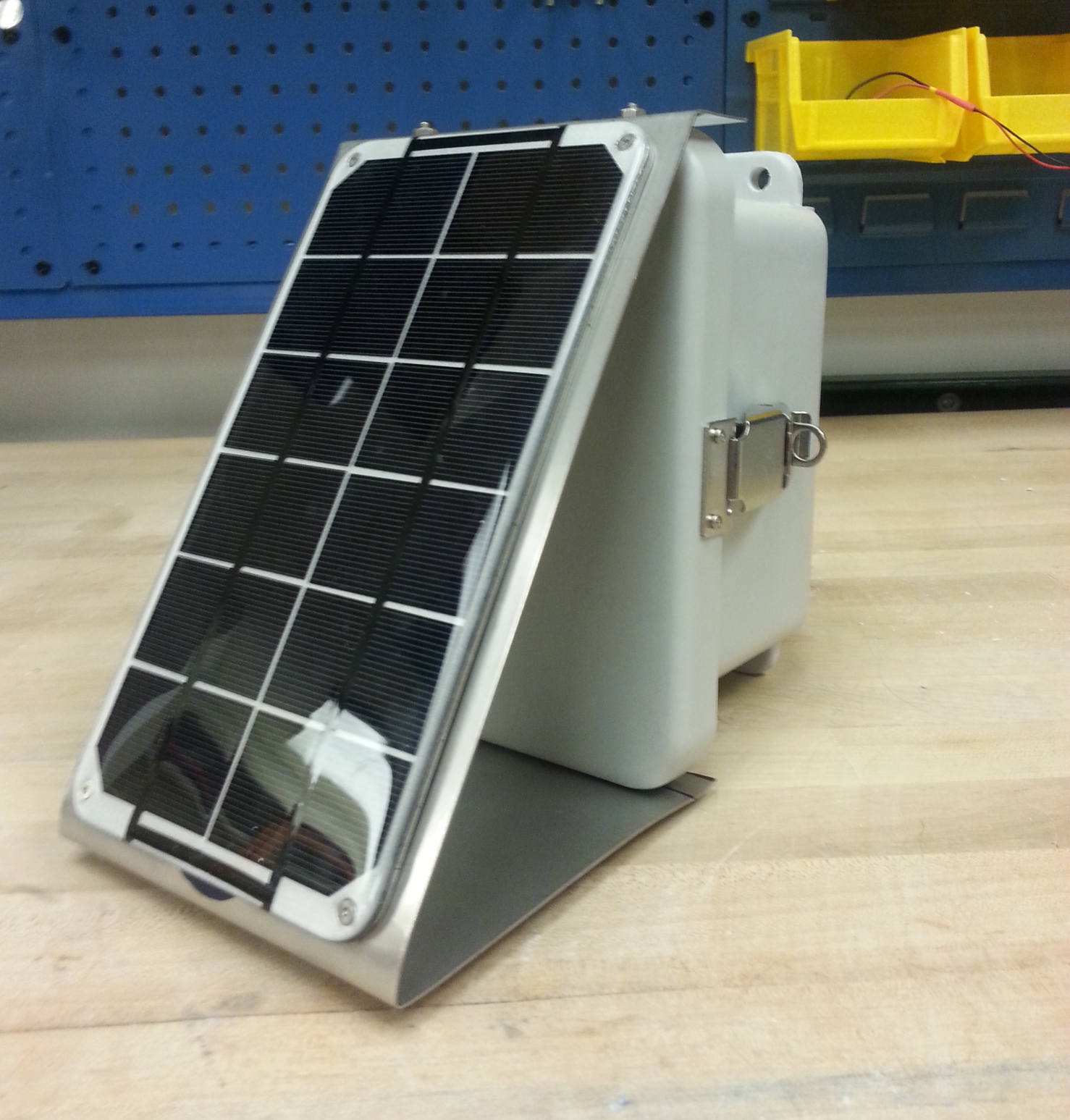
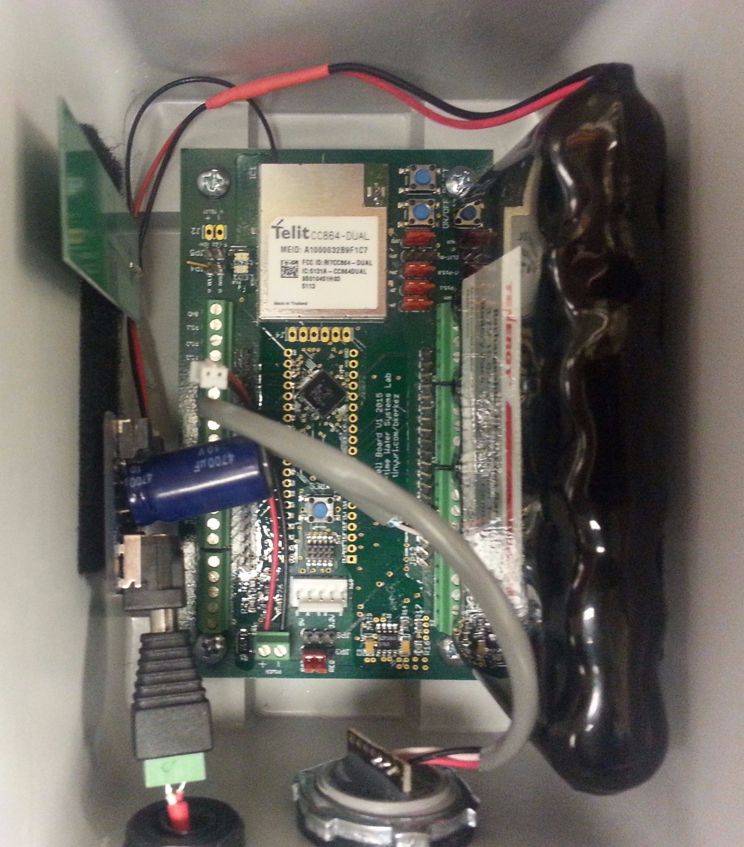
To give you some context, I’ll provide a brief overview of the sensor hardware. We use a custom-built sensor node for all field applications. This means that the printed circuit board (PCB), and the firmware (the code that runs on each sensor node) are designed and implemented in-house. Designing our own hardware and firmware allows for tight integration with our server backend, and ensures that our devices meet our specific research needs (plus it's just more fun that way).
Communications
Each node uses a cellular connection to transmit data to and from a remote server. The node features a cellular module (the same technology that’s in your cell phone), which allows bi-directional communication across 2G, 3G or 4G networks. Bi-directional communication offers a number of advantages, one of the most important of which is the ability to remotely change the sampling frequency on the node, conserving power during dry days, and achieving better temporal resolution during storms. Data is sent to our remote server using ordinary HTTP POST requests (the same protocol you use to access websites every day).
Power
The node features a rechargeable Li-ion battery and a 6V solar panel, which enable the node to remain in the field indefinitely without battery replacement.
Sensors
This particular version of the sensor node comes equipped with an ultrasonic depth sensor, which is used to measure the distance to a water surface beneath the node. The sensor works by emitting a series of clicks and measuring the time it takes for the sound pulse to return (essentially the same principle that a bat or dolphin uses to sense the distance to an object). The range for this particular sensor is 500 mm – 10 m.
Overall, the cost for each sensor node is approximately $350 (not including the sensor), or $500 (including the sensor), with a $6 / mo. data plan.
Deployment
Ok! Now that we got that out of the way, let's talk about the deployment process. In the first part of this section, I'll discuss the parts needed to construct the mounting frames, and I'll briefly describe the process of putting the frames together.
In the second part of this section, I'll discuss the procedures for deploying a bridge-mounted sensor node. The sensor node will be attached to a bridge deck using four threaded rods fixed in anchoring epoxy. The procedure for deploying the node is simple. First, the site is surveyed and the locations of the mounting holes are marked. Next, the mounting holes are drilled into the bridge deck using a concrete drill. After drilling, the mounting holes are filled with anchoring epoxy, and the threaded rods are inserted. Finally, after the epoxy has cured, the mounting frame is placed over the threaded rods and the sensor is activated.
Buying the mounting hardware
Before we get started, we'll need the proper materials. The following table gives the parts and prices needed to construct mounting frames for five nodes (all products listed are from McMaster-Carr). Note that for some parts, I've included allowances for spares.
| Full part name | McMaster ID | Price / Unit | Qt Needed per Node | Qt / Unit | Total Units Needed | Total Price |
| Steel strut channel, slotted, 1-5/8″ x 1-5/8″, galvanized, 10′ length | 3310T64 | $54.48 | 0.6 | 1 | 3 | $163.44 |
| Strut channel accessory, 90 degree angle bracket, 4-hole, galvanized steel | 33125T146 | $4.85 | 3 | 1 | 15 | $72.75 |
| Strut channel accessory, U-style bracket for 1-5/8″ D Strut, galvanized steel | 33125T194 | $5.38 | 3 | 1 | 15 | $80.70 |
| Corner brace for strut channel, 2 hole, galvanized steel, 8″ long | 3574T22 | $10.35 | 1 | 1 | 5 | $51.75 |
| Strut Channel Nuts with Springs, Zinc-Plated, 1-5/8″ High Channel, 1/2-13 Thread Size | 3259T15 | $7.09 | 12 | 5 | 12 | $85.08 |
| Type 316 stainless steel hex head cap screw, 1/2″-13 thread, 1″ long, fully-threaded | 93190A712 | $4.99 | 14 | 5 | 14 | $69.86 |
| Type 316 stainless steel flat washer, 1/2″ screw size, 0.531″ID, 1.250″ OD | 90107A033 | $9.71 | 14 | 25 | 4 | $38.84 |
| Type 316 Stainless Steel Hex Nut, 1/2″-13 Thread Size, 3/4″ Wide, 7/16″ High | 94804A340 | $4.51 | 3 | 10 | 2 | $9.02 |
| Type 316 stainless steel hex head cap screw, 5/16″-18 thread, 3/4″ long, fully threaded | 93190A581 | $3.77 | 4 | 10 | 2 | $7.54 |
| Type 316 Stainless Steel Flat Washer, Oversized, 5/16″ Screw Size, 0.344″ ID, 1.250″ OD | 91525A230 | $5.43 | 4 | 10 | 2 | $10.86 |
| Type 316 Stainless Steel Hex Nut, 5/16″-18 Thread Size, 1/2″ Wide, 17/64″ High | 94804A030 | $5.92 | 4 | 50 | 1 | $5.92 |
| ~$600-$700 |
Creating the frames
The first step in the deployment process is to construct the mounting frames that attach the sensor nodes to the bridge deck.
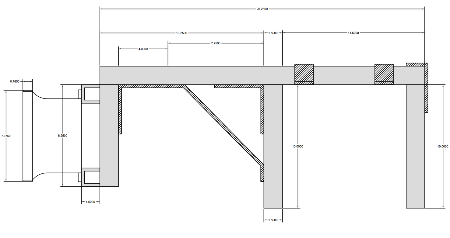
These frames are constructed using galvanized steel strut channels, and are attached to the sensor nodes via screws that fit into the bottom of the sensor enclosure. Note that we use galvanized steel because it provides a good balance between strength and corrosion resistance. For outdoor applications, non-galvanized steel should not be used. Aluminum is also a valid choice, except that one must be careful to choose compatible fittings such that the screws and nuts do not corrode. A schematic for our frame is shown below (note that the rightmost vertical bar is optional, and is not used for the nodes that we deployed):
For each frame, you will need:
- Strut channel, 4-slot length (x2)
- Strut channel, 8-slot length (x2)
- Strut channel, main section (length will depend on the size of the mounting surface)
- Corner brace (x1)
- 90-degree angle bracket (x2)
- U-style bracket (x2)
- Strut channel nuts, 1/2″-13 thread (x12)
- Hex head cap screw, 1/2″-13 thread, 1″ long (x14)
- Washer, 1/2″ screw size (x14)
- Hex nut, 1/2″-13 (x2)
- Hex head cap screw, 5/16″-18 thread, 3/4″ long (x4)
- Washer, 5/16″ screw size (x4)
- Hex nut, 5/16″-18 (x4)
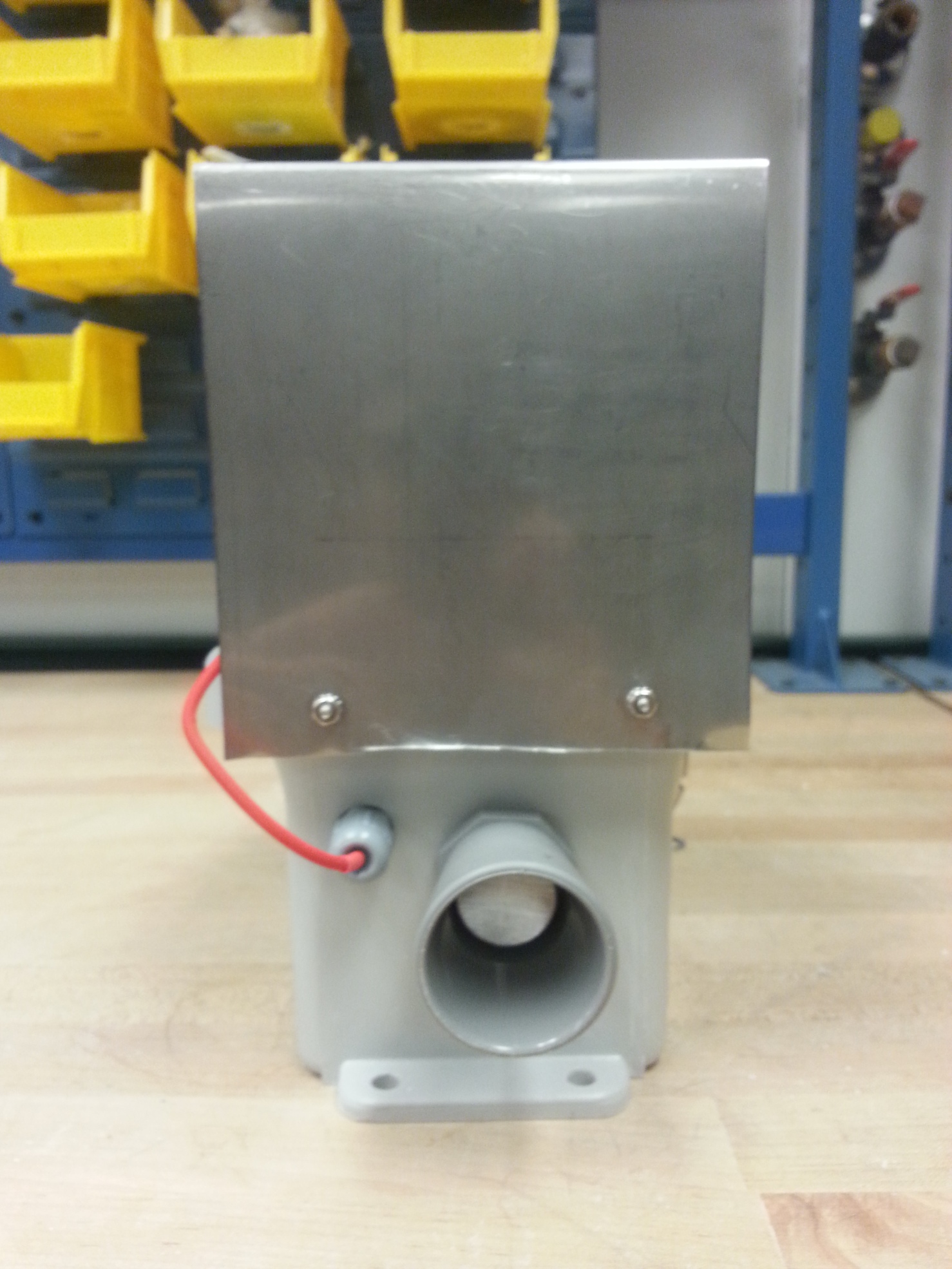
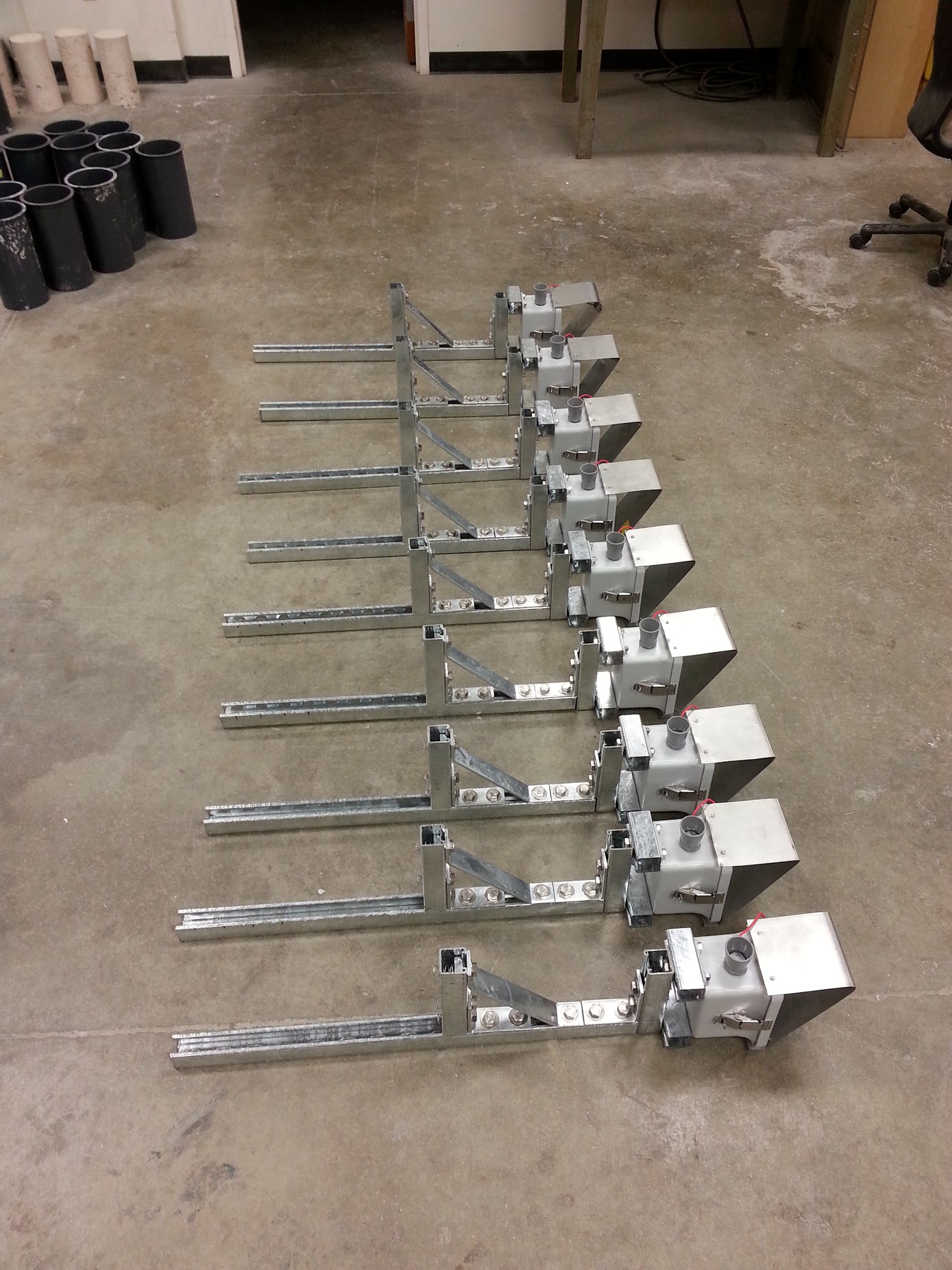
The strut channel pieces will need to be cut to size using a band saw. The process for constructing these frames is fairly self-explanatory. Simply attach the pieces together using the appropriate fittings, nuts and bolts. Strut channel pieces are connected to each other using the 1/2″-13 thread size connectors, while strut channel pieces are connected to the sensor enclosure using the 5/16″-18 thread size connectors. The two 1/2″-13 hex nuts are used to secure the U-style connectors to the frame. You can see the finished product (excluding the U-style connectors) below:
Preparing the sites
The next step is to visit each site, find an appropriate location for the sensor, and mark the locations where the mounting holes will be drilled.
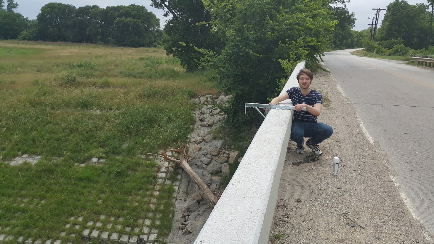
The easiest way to mark the drill hole locations is to bring the mounting frame, and place it over the bridge barrier. The four holes in the two U-style connectors can then be used as a stencil for the drill hole locations.
Now that the site has been inspected, we are ready to start drilling!
Drilling the mounting holes
The following tools will be needed to drill the mounting holes at the site:
- Concrete drill
- Portable generator
- 1/2″ diameter 4″ length stainless steel threaded rods (x4)
- 5/8″ concrete drill bit (9/16″ will also work)
- Painter’s tape (for marking drill bit length)
- 10 oz. caulking gun
- High-strength anchoring epoxy
- Eye protection
- Face mask
The steps for preparing the mounting holes are as follows:
- First, put on your eye protection and face mask (safety first!).
- Insert the 5/8″ concrete drill but into the concrete drill. We will be drilling a 3″ hole in the concrete, so use painters tape to mark the drill bit 3″ from the tip of the bit. Note that the diameter of the drill bit should be 1/16″-1/8″ larger than the diameter of the threaded rod (which in this case is 1/2″).
- Drill a 3″ hole at each of the four marked locations on the concrete barrier, using the painter’s tape to judge when 3″ have been drilled.
- After drilling, check the alignment of the holes by placing the mounting frame over the holes and inserting the threaded rods.
Next, we will be filling the mounting holes with epoxy and securing the threaded rods.
Securing the threaded rods and installing the frame
The following tools will be needed to secure the threaded rods:
- High-strength anchoring epoxy
- 10 oz. caulking gun
- Flashlight
- Compressed air
- 1/2″ diameter nylon brush
- Rag or shop towels
- Impermeable gloves
- 3/4″ socket wrench
- 1/2″ diameter 4″ length stainless steel threaded rods (x4)
- 1/2″ diameter hex nuts (x4)
- 1/2″ diameter washers (x4)
The steps for securing the threaded rods are as follows:
- Ensure that you are wearing impermeable gloves (you really don’t want to get epoxy on your hands).
- Clean each of the mounting holes thoroughly using the compressed air and the nylon brush. We want to make sure that the amount of concrete dust inside the holes is at a minimum. Excessive dust will prevent the epoxy from binding securely to the concrete. You can use a flashlight to inspect the inside of each mounting hole.
- Insert the tube of anchoring epoxy into the caulking gun and remove the seal.
- Depress the trigger on the caulking gun and squeeze some of the anchoring epoxy into a throwaway container. Continue to squeeze out the epoxy until the epoxy is thoroughly mixed (the degree of mixing is indicated by the color of the epoxy exiting the tube).
- Once the epoxy is thoroughly mixed, insert the caulking gun into a mounting hole and fill the hole approximately halfway with epoxy.
- Insert the threaded rod into the hole while slowly rotating it clockwise. This ensures that the epoxy properly binds to the threads. If excess epoxy spills out of the hole, make sure to clean it up quickly with a rag.
- Keep in mind that the epoxy will become hard very quickly, meaning that you have limited time to complete this step.
- Repeat the process for each hole.
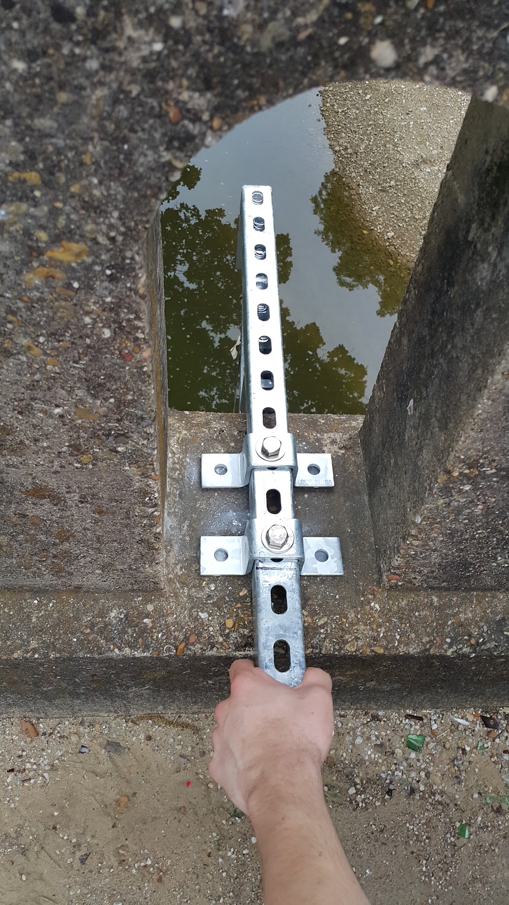
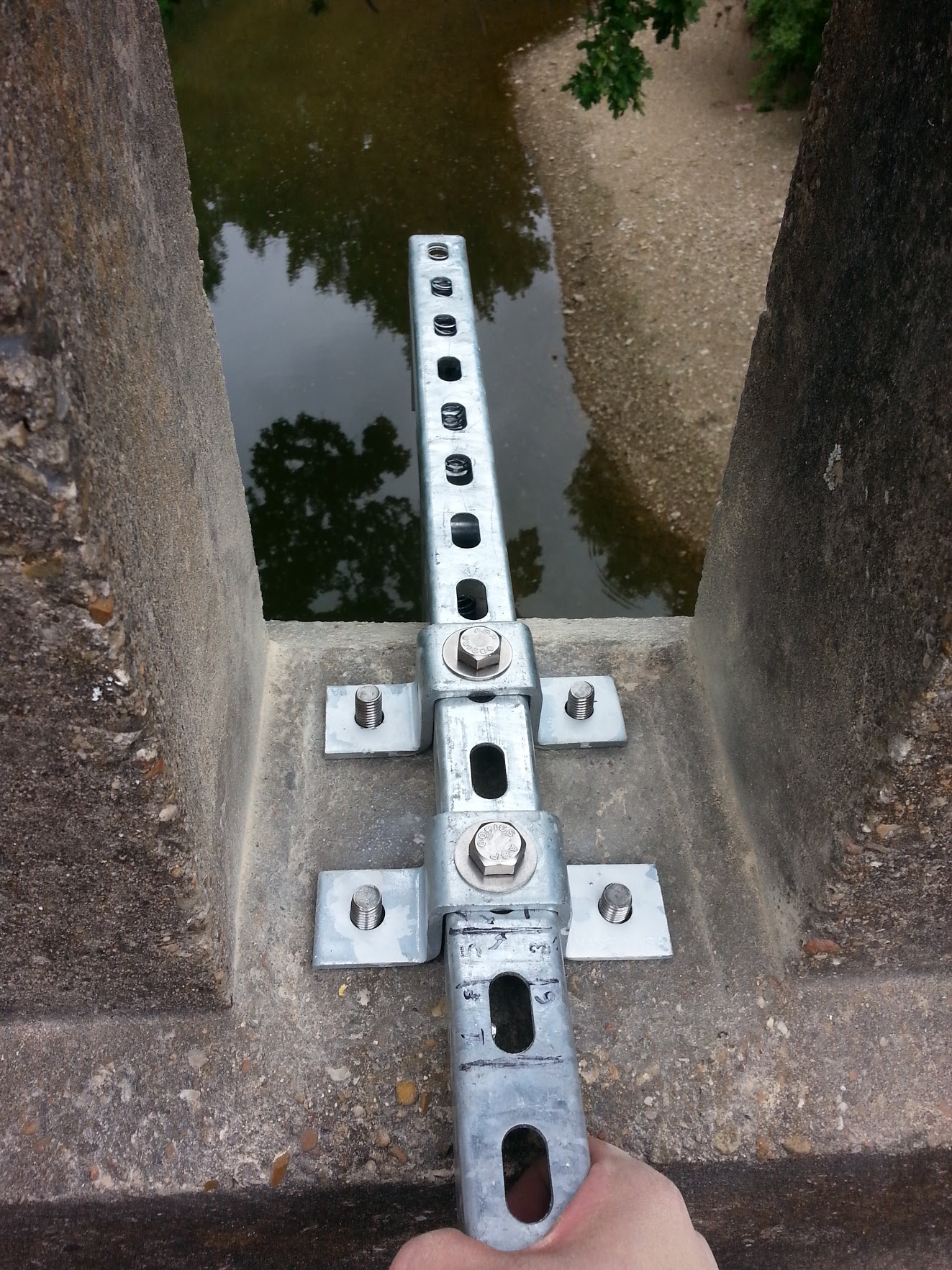
- To ensure that the threaded rods stay aligned, place washers over the threaded rods and then place the two U-style connectors over the threaded rods while the epoxy cures. A section of strut channel can be placed through the U-style connectors to align them. The washers are used to guarantee that the U-style connector does not bind to the epoxy underneath.
- Wait approximately four hours for the epoxy to cure.
The result should look something like this:
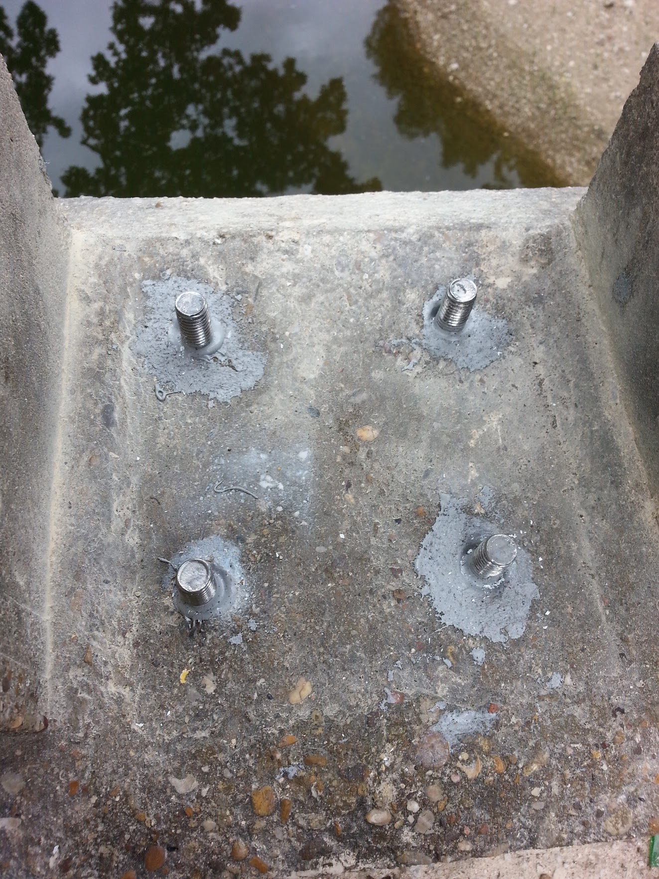
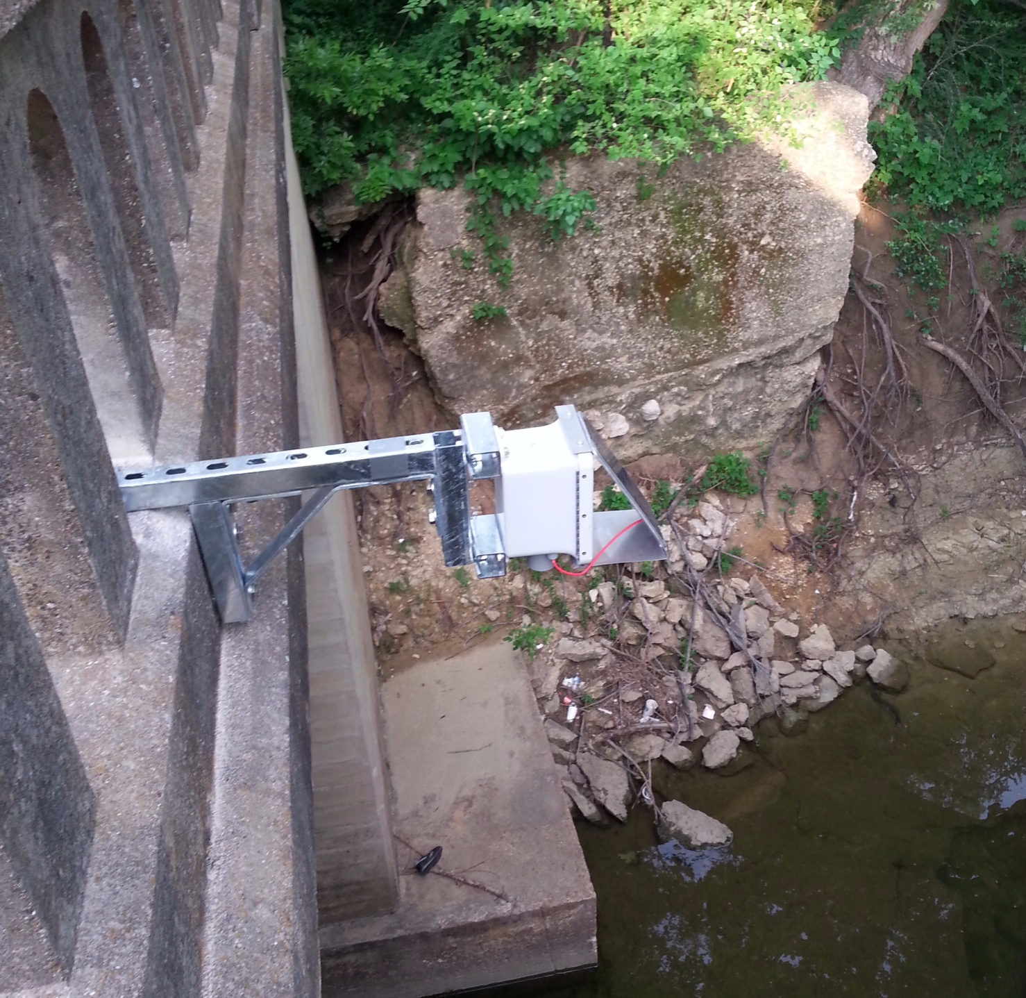
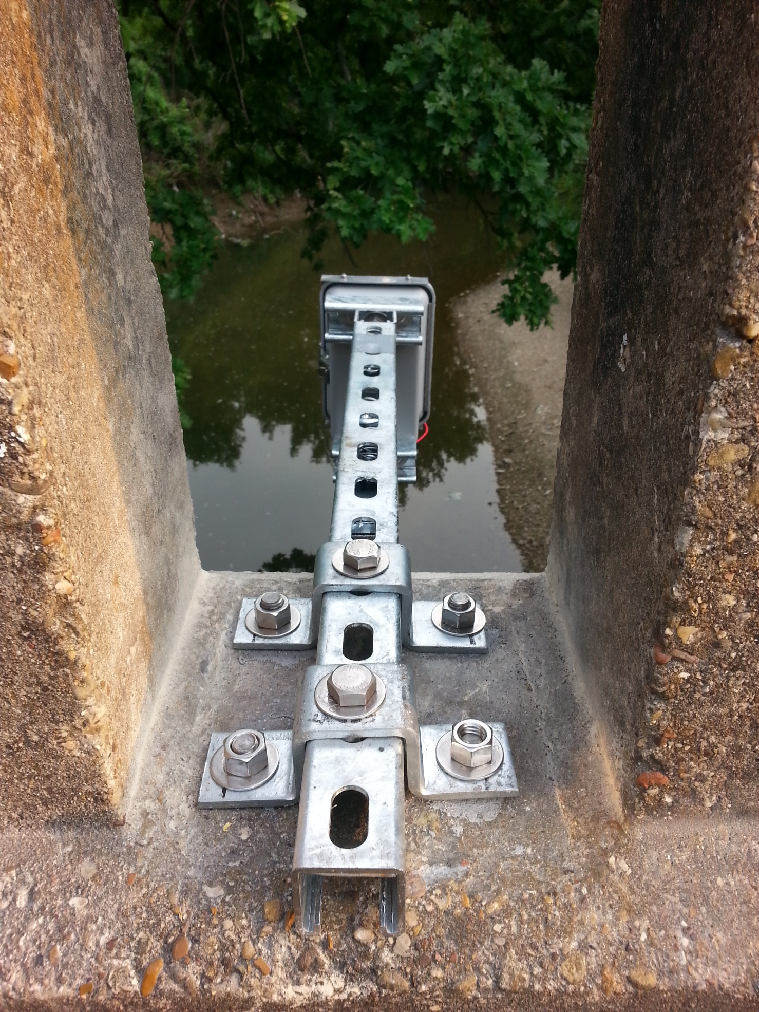
After the epoxy cures, place the frame over the threaded rods and tighten the apparatus in place using a 3/4″ socket wrench.
And there you have it!
Now that that’s all done, you can sit back, relax, and watch your data stream.

Until next time,
MDB
For more info, check out open-storm.org