Join us in Austin, TX this summer for the ESIP July Meeting! Register today.
FUNding Friday Project: Automated sensor firmware generation using SensorML

Hey ESIP,
This blog post gives an update on my FUNding Friday project: a proof-of-concept platform for automated sensor firmware generation. The results of the project are available on Github. Note that development is still ongoing
Project overview
This project aims to make it possible for newcomers to program and deploy their own sensors by creating a “plug-and-play” system for sensor firmware development. This “plug-and-play” system is realized through a code generation tool that ingests machine-readable sensor metadata and outputs ready-to-use sensor drivers. Through this open-source tool, I hope to enhance the accessibility of sensing for professionals and hobbyists alike.
Despite recent efforts to improve the accessibility of embedded systems, driver development for sensors is still largely a manual operation. This means that whenever a user wants to add a new sensor to their platform, they must (i) read the sensor’s user manual to determine relevant protocols and technical information and, (ii) write a driver for the sensor–generally in a low-level programming language like C. This process results in duplication of effort, poor standardization and limited potential for code reuse. More importantly, the need to manually write firmware excludes those with limited programming experience.
To address this problem, I created a proof-of-concept code generation tool that automatically creates sensor firmware by (i) ingesting machine-readable documents that provide relevant technical information, and (ii) outputting usable source code that can be flashed to the platform of interest. The project draws on previous work from the EnviroSensing cluster, including the sensorML standard (developed by Mike Botts), and the XDOMES project (led by Janet Fredericks).
The project culminated in the open-source firmament library, available on Github.

Library overview
Prerequisites
Before using firmament you will need the following hardware and software:
Hardware
firmament currently only supports Cypress PSoC devices. To use this library, you will need to purchase a device that uses a PSoC 5LP processor.
A Cypress prototyping kit can be purchased here for ~$10
You will also need a sensor that uses one of the compatible protocols:
- Analog
- TTL
- RS-232
- RS-485
- I2C
Note that SDI-12 support is currently in development as well.
Software
To use the firmament library, you will need:
- PSoC Creator 4.1 or greater.
- Python 3.6 or greater.
Principle
firmament generates sensor and actuator drivers for use in embedded systems. The code generator uses two types of documents: driver documents and configuration documents. These documents can be formatted as sensorML, or as a simplified yaml document.
Driver documents
Driver documents are used to generate drivers for individual sensors or actuators.
These documents provide information about the sensor's communication protocols, and describe any information needed to intepret the data stream. Note that each sensor should have only one “standard” driver document.
An example (in simplified yaml format) is shown below. SensorML is also supported, but I include the yaml version here because it is more readable.
# Component description
identifier : "urn:maxbotix:mb7383"
manufacturer : "Maxbotix"
name : "MB7383 HRXL-MaxSonar-WRLST"
description : "High performance ultrasonic rangefinder"
alias : "mb7383"

# Metadata
pinout:
    - "temperature sensor connection"
    - "pulse width output"
    - "analog voltage output"
    - "ranging start/stop"
    - "serial output"
    - "positive power (vcc)"
    - "ground"

# Data
output_variables:
    - name: "distance"
      units: "mm"
      data_range : [500, 9999]

# Communications
default_communication_protocol : "ttl"
firmware:
    ttl:
        static:
            data_bits : 8
            parity : "none"
            parity_api_control : 0
            stop_bits : 1
            flow_control : "none"
            logic_level : "high"
        dynamic:
            baud : 9600
            on_time : 800
            buffer_len : 5
            nvars : 1
            skipchars : 86
            str_start :
                - 'rR'
            str_end :
                - 'r'
            label :
                - "maxbotix_depth"
            invalid :
                - 9999
            default :
                - -9999
        components:
            - "generic_uart_rx"
            - "power"
    analog_sar:
        scale_factor_numerator: "vcc"
        scale_factor_denominator: 10240
        resolution_bits : 12
        conversion_rate_sps : 631579
        sample_rate : "free running"
        clock_source : "internal"
        input_range: "vss_to_vref"
        reference: "int_ref_bypass"
        components:
            - "analog_sar_signal"
            - "power"
    analog_delsig:
        scale_factor_numerator: "vcc"
        scale_factor_denominator: 10240
        resolution_bits : 20
        components:
            - "analog_delsig_signal"
            - "power"
Let's concentrate on the ‘communication protocols' section. This section tells the firmware how we're going to communicate with the device. The sensor supports three different protocols: TTL (digital), Analog with a Successive Approximation ADC, and Analog with a Delta-Sigma ADC. For more info on ADCs, see my previous blog post.
Under the TTL protocol, you'll see two different sections.
- The ‘static' section lists parameters needed for the device's internal UART: for instance, the number of data bits that it should expect to see.
- The ‘dynamic' section lists parameters that are needed to read and interpret output from the sensor, like the parsing logic for the incoming bits. In this case, we expect each reading to consist of a string that is formatted as follows: “rR <reading> r”.
- Finally, under ‘components', you can see what external components the sensor requires. In this case, the sensor needs a pin for power, and a pin for transmitting the data.
Example yaml driver documents can be found in `firmament/peripherals/yaml`
Example sensorml driver documents can be found in `firmament/peripherals/sensorml`
Configuration document
A single configuration document is used to specify desired sensors, desired communication protocols, and the ports that they will use. This configuration document is unique to each build.
platform: 'cypress'
external:
    - identifier : "urn:maxbotix:mb7383"
      communication_protocol : "ttl"
      pins:
          power : '12,6'
          generic_uart_rx : '12,7'
    - identifier : 'urn:battery_internal'
      communication_protocol : 'analog_delsig'
      pins:
          power : '12,1'
          analog_delsig_signal : '0,0'
- ‘platform' tells us that the code generator will compile the build for a Cypress platform.
- ‘external' contains a list of sensors, along with desired settings. For this build, we have specified two sensors: a maxbotix depth sensor (digital), and a battery voltage sensor (analog).
- For the maxbotix sensor, we have selected the TTL (UART) protocol, and we have told the code generator to configure the firmware so that the maxbotix sensor is powered off of pin 12:6 and that incoming data is read from pin 12:7.
- For the battery voltage sensor, we have selected the analog protocol with a Delta-Sigma ADC, and we have told the code generator to configure the firmware so that the sensor is powered off of pin 12:1 and that incoming data is read from pin 0:0 (internal).
An example configuration document can be found in `firmament/device_config.yml`
Installation
Cloning from github
You can download the project using git:
git clone https://github.com/mdbartos/firmament
You can also download a zip file from the github repo.
Running the code generator
Navigate to the root directory of the repo and run:
python firmament/build/cypress.py firmament/device_config.yml
This will generate and compile the firmware into a binary. This binary can be flashed to a Cypress PSoC device using PSoC Creator or PSoC Programmer. Note that only Python 3 is supported.
See the README on Github for more information about dependencies.
Flashing the device
If you are using the Cypress prototyping kit, simply connect the USB input to your computer. Then open up PSoC Creator.
Let's make sure that the board is recognized. From the toolbar, select `Debug -> Select debug target`.

Now select the `Port setting` button from the window that pops up.
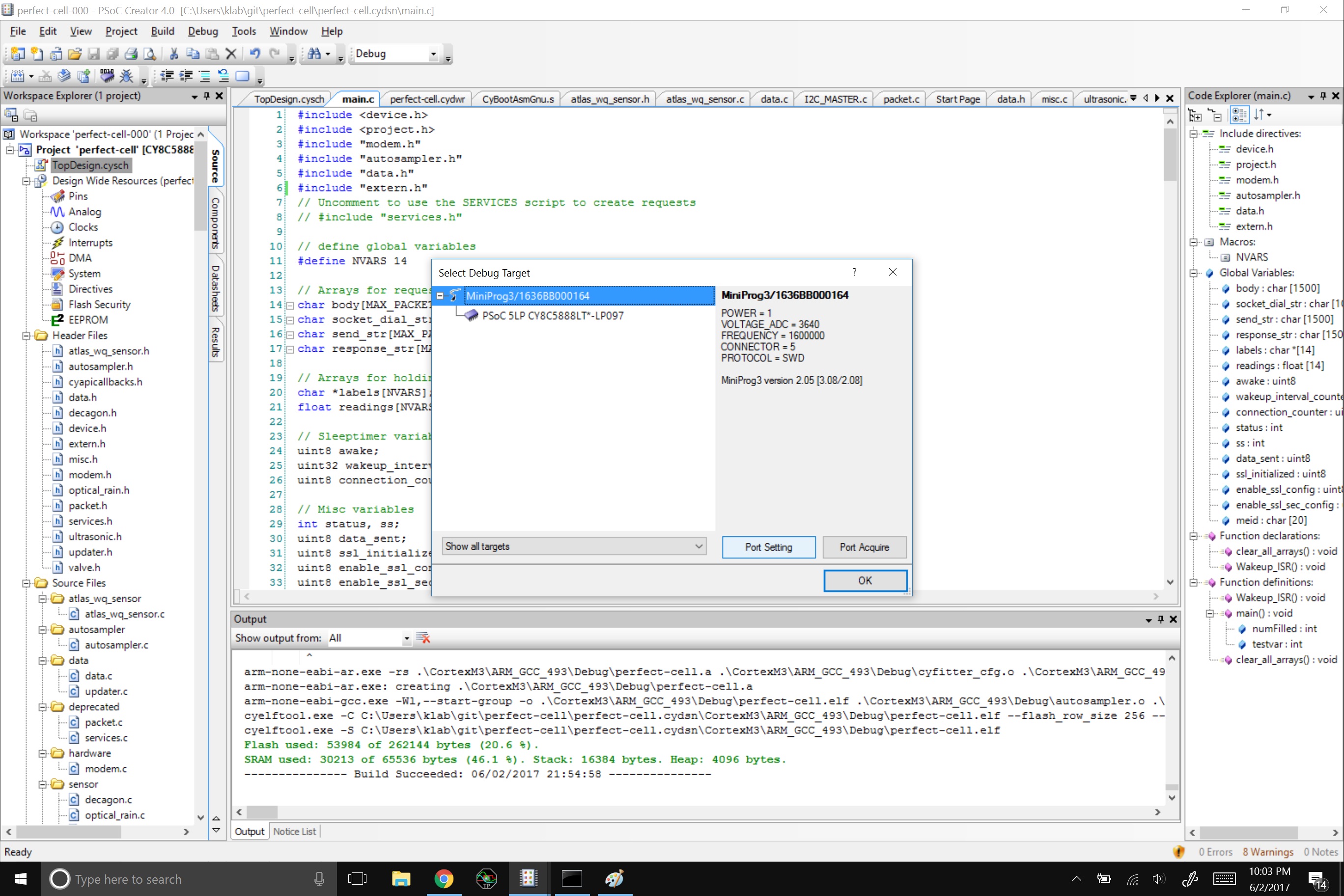
The connector should be the 5-pin type.
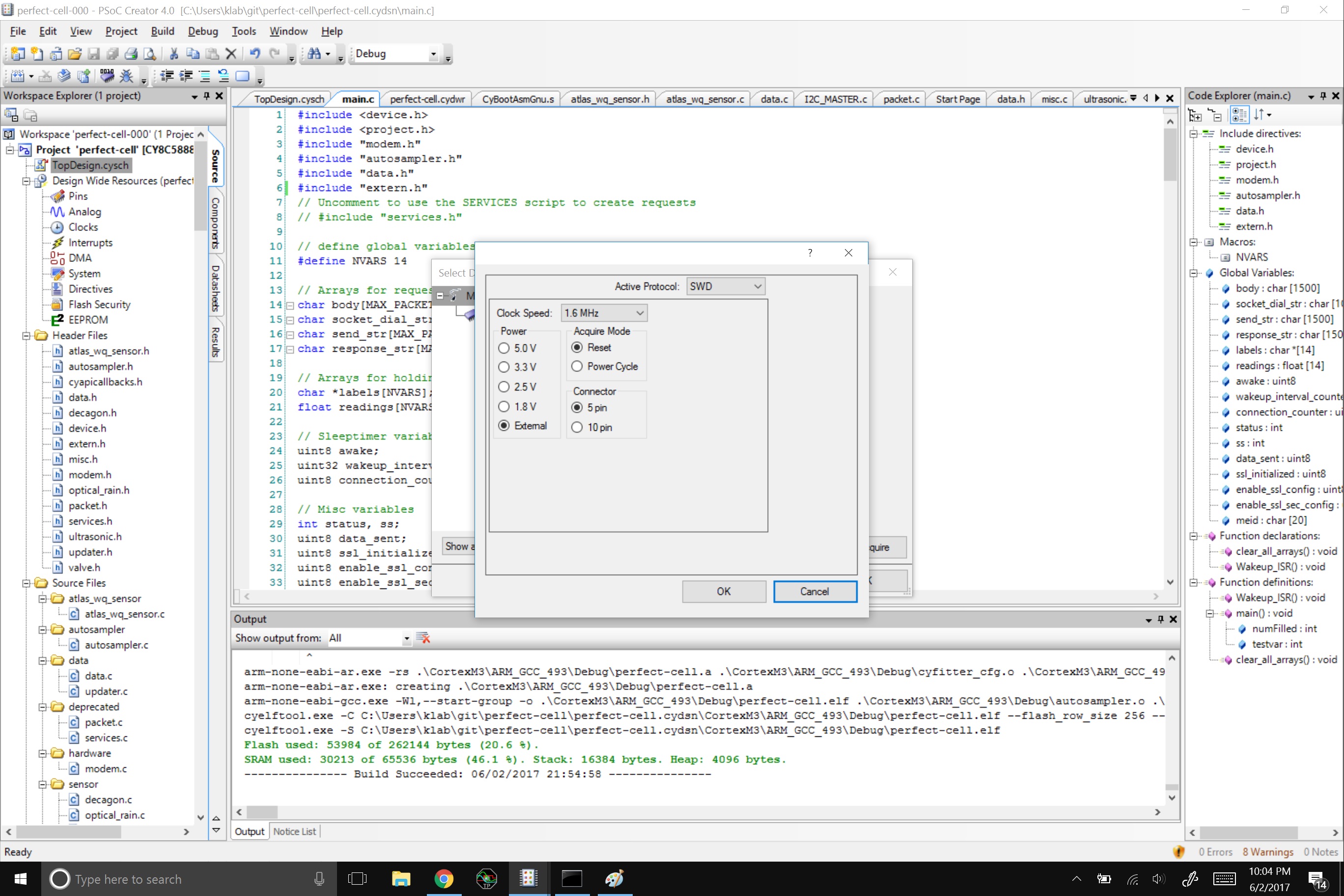
Now connect to the device.

Finally, select `Debug -> Program` and program the device. You should see a message that says `Ready` once the device is successfully programmed.

And that's it!
Thanks for following along, and let me know if you have any questions about using my repo!

